[Verilog] Dataflow Modeling
Continuous Assignments
연속적인(Continuous) 할당은 dataflow의 가장 basic한 상태이다.
값은 net(wire)로 연결시켜주어야한다.
- 특징
LHS(left hand side) : a (concatenated) scalar 나 vector여야한다.
RHS(right hand side) : reg or net or function calls
항상 작동된 상태이며, 우변의 값이 변경되면 실행된다. - 코드 작성 스타일
implicit assignment, declaration보다 explicit declaration 형태로 작성하는 것을 추천한다.
  // explicit net
  wire out;
  assign out = in1 & in2;

  //implicit net
  wire out = in1 & in2;
+) 추가 설명 : clock이나 다른 사건들과 관련없는 단순히 연결된 것을 기술할 때 사용함. 그래서 initial이나 always와 함께 사용하지 않음.
Gate Delay
assignment에 delay를 적용시킬 수 있다.
- Inertial delay ( 관성지연 )
an input pulse that is shorter than the delay of the assignment statement does not propagate the output
즉 delay 값이 10으로 설정되면 5로 출력되는 것 등을 noise로 취급해 처리하지 않는다.
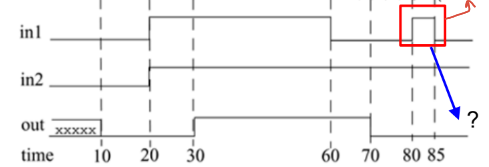
implicit continuous assignment delay는 delay와 할당을 모두 처리해준다.
wire #10 out = in1 & in2;

//위의 implicit 표현은 아래 표현과 같다.
wire out;
assign #10 out = in1 & in2;
Expressions, Operands, and Operators
- expression : operands와 operators로 결합시켜 결과를 생성할 수 있다.
- operand : 데이터 타입 하나로 만들 수 있다.
constants, integers, nets, registers, times, function calls … - operator : act on the operands to produce desired results
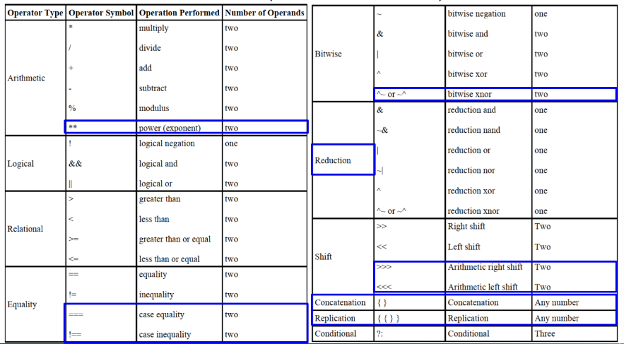
일반적으로 우리가 아는 연산자와 유사하며, 파란 표시 된 연산자는 특별하거나 추가된 것이니 잘 봐둔다.
1. ** : power(exponent)
2. === : case equality
3. ! == case inequality
4. ^~ (~^) : bitwise xnor
5. >>> : arithmetic right shift
6. <<< : arithmetic left shift
7. { } : concatenation
8. { { } } : replication (응답)
이미 우리가 프로그래밍을 많이 해봤기 때문에 당연한 일이다. 그러니 편하게 알고 넘어가자.
Arithmetic Operators
- binary operators (two operands)
Multiply, divide, add ,subtract, power, modulus
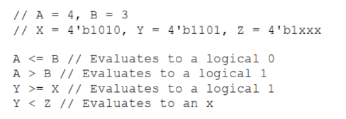
  A = 4'b0011;
  B = 4'b0100;
  D = 6; E = 4; F = 2;

  A * B;
  D / E;
  A + B;
  B - A;
  F = E ** F;
x (미결정) 이 한 bit라도 포함되어 있으면 전체 연산결과는 x이다.
modulus operation 과정에서 부호는 앞의 숫자 (나누어지는 수) 따라가면 된다.
- unary operator (one operand)
+, - : can work as unary operator and take a higher precedence
negative numbers : integer type이나 real number로 사용해야한다.
<size>’<base><number> 형식으로 상용하면 unsigned 2’s complement number로 변환하기 때문에 원하는 결과를 얻지 못한다.
Logical Operators
and (&&), or (||), not (!)
logical operators always evaluate to a 1-bit value(0, 1, x)
operand가 x, z라면 x와 동등하게 여기며, 보통 거짓으로 처리한다.
A = 3; B = 0;
A && B
A || B
!A

a1 = 2'b0x; //xx
a2 = 2'b10; //10
al && a2 // xx && 10 -> x0 -> 0
Relational Operators
relational operators : >, <, >=, <= 등
x나 z가 operand로 들어오면 x를 반환한다.
module xcompare;
    reg a, b;
    initial
    begin
        a = 2'bxx;
        b = 2'b11;
        $display (a > b, " ",a < b); //output : x x
        $finish;
    end
endmodule
Equality Operators
Equality operators : ==, !=, ===, !==
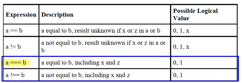
logical equality, inequality 는 결과 값으로 x (미결정)이 나올 수 있다. 하지만, case (in)equality 는 x가 나올 수 없다.
// N = 4'b1xxx, Z = 4'b1xxz
Z === N // b1xxz === b1xxx -> 0 (all bit not match)
Z == N  // output : x
Bitwise Operators
Bitwise operators : ~, &, |, ^, ^~(~^)
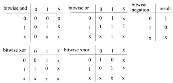
// X = 4'b1010, Y = 4'b1101, Z = 4'b10x1

~X // 0101
X & Y // 1010&1101 -> 1000
X | Y // 1010|1101 -> 1111
X ^ Y // 1010^1101 -> 0111
X ~^ Y // 1000
X & Z // 1010&10x1 -> 10x0
X & Y // 1101&10x1 -> 1001
Reduction & Shift Operators
- reduction(축소) operators : & , ~& , | , ~|
오직 하나의 피연산자를 취할 수 있다.
자신의 bit를 모두 꺼내서 연산을 한다.
// X = 4'b1010

&X // 1&0&1&0 -> 0
|X // 1|0|1|0 -> 1- shift operators
arthimetic이 붙으면 오른쪽으로 shift할 때 msb를 고려하여 연산을 해준다.
<< 와 <<< 은 기능적으로 차이가 없다.
shift operators : >>, <<, >>>, <<<
Concatenation & Replication Operator
- Concatenation operators
concatenation operator : { , }
multiple operand들을 서로 붙여주는 역할을 한다.
// A = 1'b1, B = 2'b00, C = 2'b10
X = {A, B} // 100
Y = {A, B, C, 3'b101} // 10010101- repetitive concatenation
앞에 상수를 붙이면 concat과정을 반복해서 진행해준다.
Conditional Operator
conditional operator : ( ? : )
연산자의 역할이 멀티플렉서의 기능과 굉장히 유사하다.
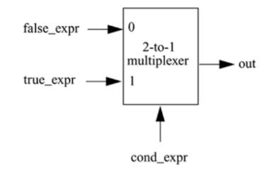
nest(중첩)이 가능하다.
Operator Precedence
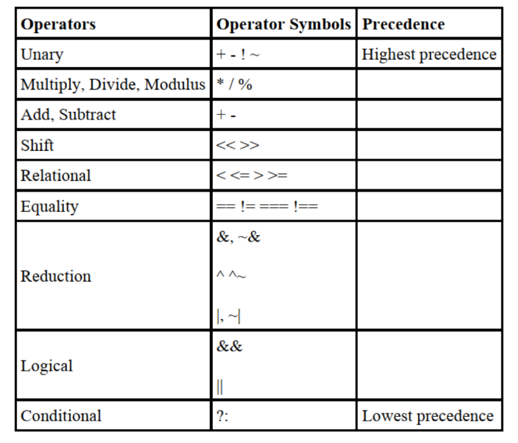
그냥 딱 식을 보고 연산자 우선순위에 따라 진행하면 된다.
2023.05.19 - [Computer Science/Verilog & HW] - [Verilog] Gate-Level Modeling
[Verilog] Gate-Level Modeling
AND/OR Gates these gates are instantiated to build logic circuits truth tables assuming two inputs BUF/NOT Gates BUF/NOT gates have one scalar input, several scalar output buf : 입력을 그대로 출력해주는 장치 노이즈가 생겼을 때 버퍼
mobuk.tistory.com
아래에 나오는 2개의 예제 (MUX, Full Adder) 에 대한 기본적인 회로, 코드는 위 글에 기술되어 있으니 참고
4-to-1 Multiplexer
- conditional operator를 이용한 구현
module multiplexer4_to_1 (out, i0, i1, i2, i3, s1, s0);

output out;
input i0, i1, i2, i3;
input s1, s0;

assign out = s1 ? (s0 ? i3 : i2) : (S0 ? i1 : i0);

endmodule
//assign out 은 아래처럼 선언할 수도 있다.
assign out = ({s1, s0} == 2'b00) ? i0 :
			({s1, s0} == 2'b01) ? i1 :
			({s1, s0} == 2'b10) ? i2 :
			i3;
4-bit Full Adder
- Dataflow operators
module fulladd4(sum, c_out, a, b, c_in);
output [3:0] sum;
output c_out;
input [3:0] a, b;
input c_in;
assign { c_out, sum } = a + b + c_in;
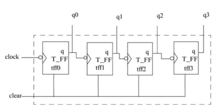
endmoduleRipple counter
ripple counter : 1bit씩 더해나가면서 돌아가는 것
0000 → 0001 → 0010 → 0011 → 0100 → … → 1111 → 0000(repeat)
- Edge-triggered D-flipflop
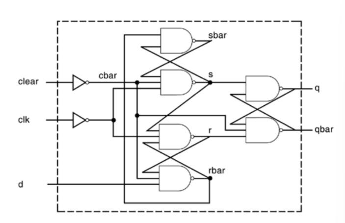
module edge_dff(q, qbar, d, clk, clear);
input d, clk;
output q, qbar, clear;

wire s, sbar, r, rbar, cbar;

assign cbar = ~clear

assign sbar = ~(rbar & s),
                s = ~(sbar & cbar & ~clk),
                r = ~(s & ~clk & rbar),
                rbar = ~(r & cbar & d);

assign q = ~(s & qbar),
            qbar = ~(q & cbar & r);

endmodule
+) 우리가 보통 알고 있는 D flip flop은 아래와 같은 모습이다.
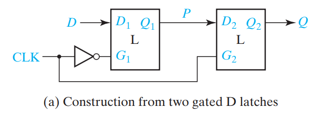
그런데 edge triggered d flip flop은 위 형태와 다른 형태이다.
SR latch의 s와 r 값에 SR latch를 넣은 모습이다.
작동방식만 간단하게 설명하겠다.
- CLK가 low → high ( rising ) : 작동하지 않는다.
- CLK가 high → low ( falling ) : input에 넣은 데이터로 기록된다.
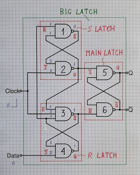
Clock에 not 이 없기 때문에 책과 다르게 rising edge임.
The trick of this clever circuit solution (7474 positive-edge triggered D latch) is to latch the inputs of an RS latch by RS latches
. So this combination can be thought of as a gated D latch with latched input gates
. While the Clock is low, the input latches are blocked; when the Clock is high, they are set by the Data input signal and can no longer be changed by it... the circuit is locked. Thus the circuit accepts the Data signal only during the rising edge.
stack overflow에서 친절한 한 사람이 falling edge triggered d latch를 기준으로 설명한 원문이다.
2. T-flip flop
T- flip flop 은 toggle flip flop이라고 불린다.
T flipflop이 쓰이는 이유는 T - flip flop이 작동될 때 0 → 1, 1→ 0 으로 바꾸어주기 때문이다.
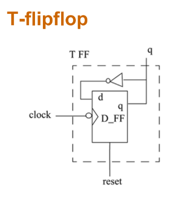
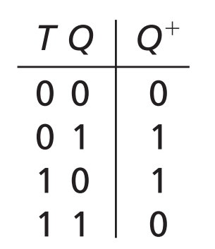
module T_FF(q, clk, clear);

output q;
input clk, clear;

edge_dff ff1(q, , ~q, clk, clear ); //qbar don't need

endmodule- Ripple Counter
마지막으로 t_ff을 원하는 bit 수 만큼 연결해주면 된다.
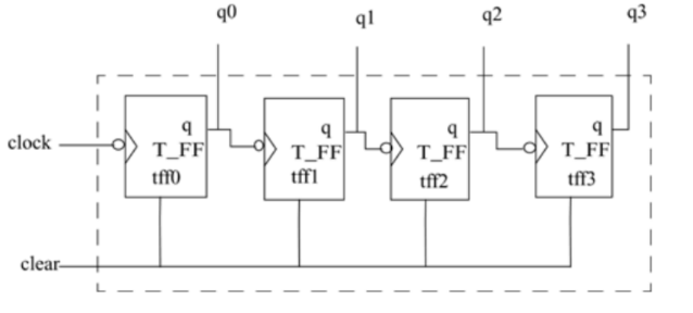
module counter (Q, , clock, clear);

output [3:0] Q;
input clock, clear;

T_FF tff0(Q[0], clock, clear);
T_FF tff0(Q[1], Q[0], clear);
T_FF tff0(Q[2], Q[1], clear);
T_FF tff0(Q[3], Q[2], clear);

endmodule
4. Stimulus(Top)
module stimulus;

reg CLOCK, CLEAR;
wire [3:0] Q;

initial
	$monitor($time, "count Q = %b Clear = %b", Q[3:0], CLEAR);
counter c1 (Q, CLOCK, CLEAR);

initial
begin
	CLEAR = 1'b1;
	#34 CLEAR = 1'b0;
	#200 CLEAR = 1'b1;
	#50 CLEAR = 1'b0;
end

initial
begin
	CLOCK = 1'b0;
	forever #10 CLOCK = ~CLOCK;
end

initial
begin
	#400 $finish;
end

endmodule